Microfluidic platform for culture and live cell imaging of cellular microarrays
Microfluidic platform for culture and live cell imaging of cellular microarrays
Project Overview
Cellular microarrays contain populations of living cells that are spatially separated from one another. Because of the numerous discrete populations, these devices are beneficial in high-throughput screening applications. We aspire to expand the utility of cellular microarrays by designing a way to integrate them with microfluidic platforms that are compatible with a standard microscope stage. Along with fitting in the stage, the platforms must be able to generate accurate concentration gradients across the integrated microarray, form a watertight seal, and be reusable in order for the devices to be effective. By accomplishing this, our client will be able to perform live-cell imaging and high-throughput analysis to determine how various culture conditions effect stem cell differentiation.
Team Picture
Team members: Sarah Reichert, Alex Johnson, John Byce, Anthony Sprangers (left to right).
Images
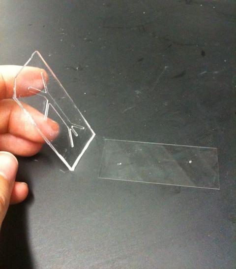
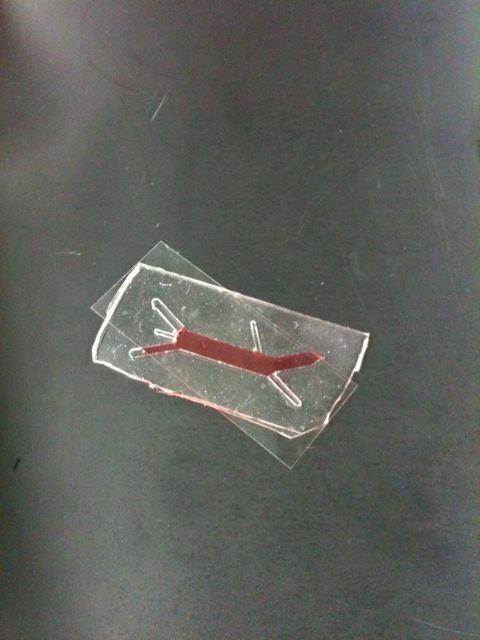
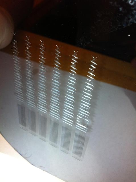
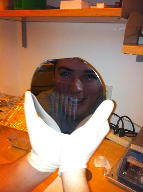
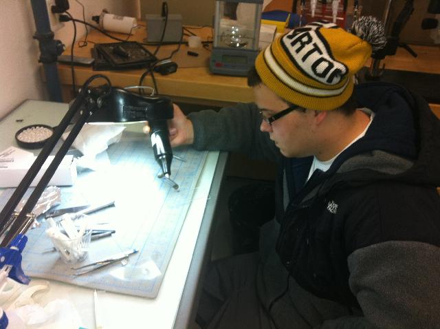
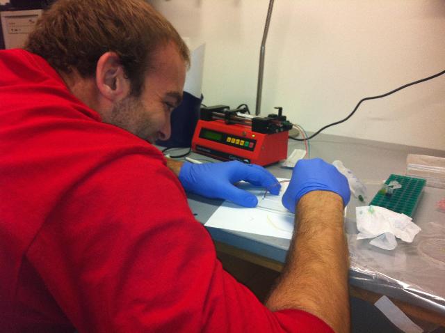
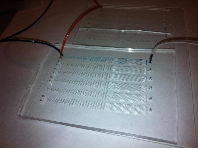
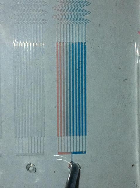
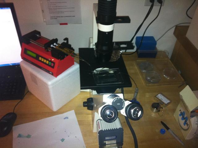
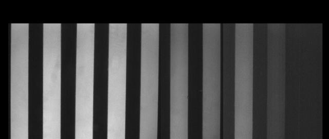
Microfluidic device created using one of Greg's (Kreeger Lab) masters. We used this to test integration of the PDMS to the glass surface to make sure we didn't have any leak issues.Red food coloring was added to water. We injected this fluid into one end of microfluidic device and allowed it to flow out the other end. From this, we determined the non-covalent adherence of PDMS to glass would be adequate enough to ensure a water tight seal throughout the cell culture channels.This is the master from which we will create our PDMS microfluidic devices. From this picture it is easy to see how small this device truly is, reference the thumb in the upper left.A zoomed out picture of the master. John using the plasma oxidizer which will irreversibly bind the PDMS (over the gradient-producing channels) to the glass underneath.AJ connecting inlet and outlet tubes to our microfluidic device so we can optically and fluorescently analyze flow properties and dynamics.Inlet tubes on the left connect to our microfluidic device which creates a gradient of the two inlet fluids; here red and blue fluids are used. Following gradient generation in the Christmas tree, the fluid then flows through the culture channels and exits through the exit port on the right.Two inlet solutions, blue and red, combine to form 10 slightly different colors as a result of the serpentine gradient-generating channels. Fluid flow from top to bottom.Fluid is flown from the left syringe pump, through the microfluidic device and exits on the right. Microscopy was used to examine every channel to ensure adequate sealing between the PDMS and glass and the PDMS and the glass coverslip.40 microM FITC-labeled Dextran (40k) in DIUF was added in inlet 1 and just DIUF was added in inlet two. This picture was taken in the cell culture channels using fluorescence imaging. Cell culture channels are 1 to 10 from left to right (the rightmost channel being barely visible which is good because only DIUF is flowing in that channel). Here we see a steady decreasing fluorescent intensity gradient from left to right indicating gradient production. Following qualitative analysis of the fluorescent intensities, we determined there may be a flaw in the diffusion leading to the leftmost four channels since fluorescent intensity values barely changed between these channels.